The Dobsonian telescope is simplicity itself: a Newtonian reflector mounted on a basic altaz mount.
Many thousands of astronomers have constructed their own Dobsonians, but the satisfaction of building your own mount is immense.
Downloads
Materials to help with the construction of your Dobsonian mount
- DIY Dobsonian mount calculations spreadsheet (Excel)
- DIY Dobsonian mount components list (PDF)
- DIY Dobsonian mount cutting template (PDF)
Materials to help with the assembly of your Dobsonian mount
- DIY Dobsonian mount diagram 01 (PDF)
- DIY Dobsonian mount diagram 02 (PDF)
- DIY Dobsonian mount diagram 03 (PDF)
- DIY Dobsonian mount diagram 04 (PDF)
The dimensions of our design are based on a 10-inch Newtonian reflector but you can work out what size components you need for any Newtonian with an aperture of 8 inches or more using the ‘Calculations’ spreadsheet in the 'Construction' zip folder available at the link above.
The mount is made from 18mm plywood, which has great strength and warp resistance.
We chose to use cheaper ‘Far Eastern’ plywood and give it a painted finish.
Alternatively, you could opt for a natural wood finish if you use the more expensive Birch plywood; this wood has a nicer grain, with fewer knots and blemishes, which gives a better result when varnishing.
Apart from a plunge router, you only need standard tools and sundries.
Construction
Power tools- A plunge router for cutting the circular components of the mount; hand drill with 1.5mm and 2mm bits to make pilot holes.
Tape measure and pencil- Accurate measurements are essential for making sure that the mount assembles to a tight tolerance.
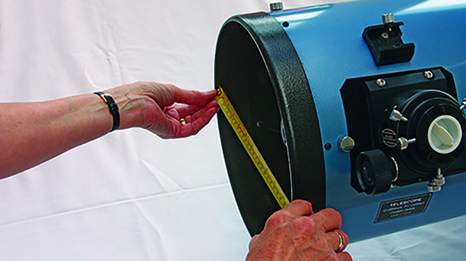
Telescope- This project assumes that you own or are going to acquire a Newtonian reflector tube with an 8-inch or greater aperture, as well as suitable tube rings and a pair of dovetail bars.
Wood- External-quality 18mm plywood is ideal for this project as it is strong and warp resistant; make the router jig out of 3mm MDF.
Assembly
Tools- A standard crosshead screwdriver is needed for much of the assembly; Allen keys and spanners are required for some of the retaining bolts.
Paint or varnish- To give the mount protection from night-time moisture to prolong its life. Make sure the product you use is intended for outdoor use.
Tape measure, protractor and pencil- For accurately marking out the positions of the various components.
Adhesives- Both PVA wood glue and epoxy resin are needed.
To begin the build, enter the nine dimensions required in the yellow boxes of our Calculations spreadsheet.
This generates the sizes for the wooden parts you need in the blue boxes.
Transfer these figures to a diagram similar to the ‘Cutting Template’ in the 'Construction' zip folder (allowing an extra margin for the altitude bearing wheels – see Step 3) and ask your timber merchant to cut the sheet for you.
You should end up with six pieces: two equal squares for the base board and rocker box base, one short rectangle for the rocker box front, one long rectangle (we’ll use this to make the box’s sides) and two larger squares for the altitude-bearing wheels.
Note that the ‘Tube to Altitude Bearing Ratio’ in the Calculations spreadsheet defines how large the altitude-bearing wheels will be.
Anywhere between 1.5x and 1.8x is fine, with larger wheels resulting in smoother operation.
Creating a jig
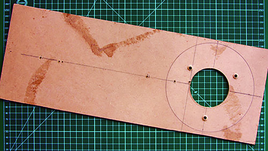
The figures produced in the red boxes in the Calculations spreadsheet are to help you make a circle-cutting jig for use with the plunge router.
This jig is vital to turning the square altitude-bearing wheel ‘blanks’ into circles.
First, cut a piece of 3mm MDF board to the dimensions given in Step 2, then mark and drill 2mm holes in the jig at positions ‘a’ to ‘e’, as indicated by the numbers in the red boxes.
Note that these positions are measured from the inner edge of the router bit.
Replace the router’s foot with this jig, then push a 2mm round nail through position ‘a’.
Place one blank on the table, mark its centre, then drill a small pilot hole.
Place the router and jig on the board, then tap the nail into the pilot hole.
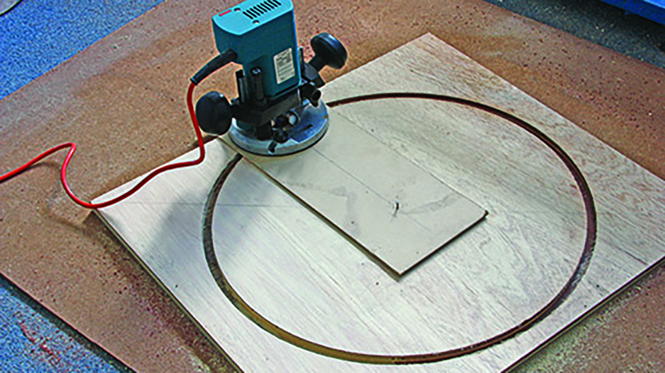
Start the router and plunge it down by just 3mm, then lock it and slowly rotate it around the nail in a complete circle.
Plunge it down a further 3mm and cut a deeper circle.
Continue until you have cut through the full thickness of the board, then repeat for the second blank.
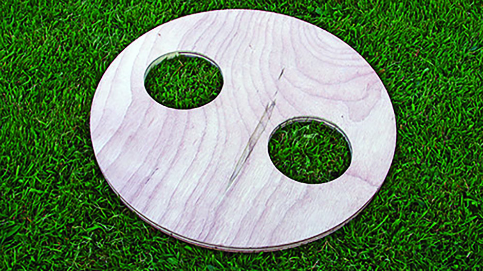
You now have two circles.
Follow one of the lines passing through the centre and mark the one- and three-quarter points; drill pilot holes on them.
Then cut two holes in each wheel, with the pilot holes at the centre and the nail in the jig at position ‘c’.
Keep the two best cut-out discs for use as ‘retainers’ later on.
Altitude-bearing wheel complete, we need to make the sides of the rocker box.
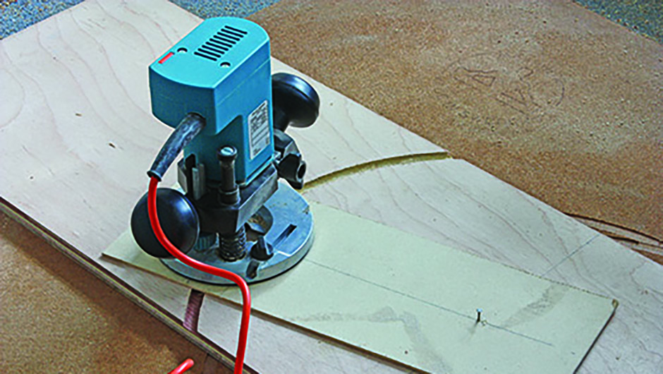
Mark the centre of the side panel sheet (the long rectangle), drill a pilot hole, then move the nail in the router jig to position ‘b’ and cut out another circle.
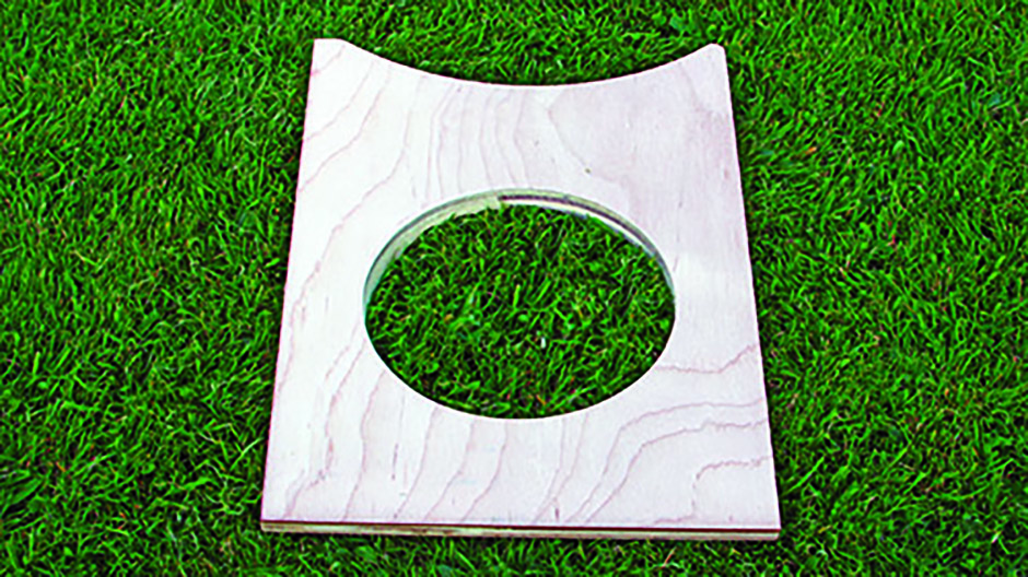
This time the circle will be incomplete, leaving you with two rocker box sides with one scalloped edge.
Mark the centre of each side and use the router to cut out further circles using position ‘e’.
Finally, cut a rectangular piece of ply 50mm deep by the width of the rocker box base for use as a brace.
Assembling the mount
In this section, we’ll be referring to the resources on the ‘Assembly’ zip folder throughout, so we recommend that you print these out before you begin.
Start by marking the centre of the rocker box base, then draw a line from one side to the other through this central point.
Do the same for your base board.
Take the base board and – using the line you just drew as the ‘horizontal’ to rest against – use a protractor and ruler to mark off the various points indicated on Diagram 1 in the 'Assembly' zip folder.
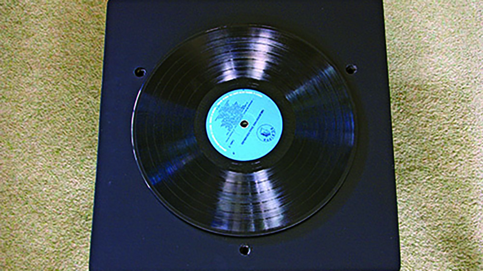
Drill the holes at the sizes specified on Diagram 1, and then a 12mm hole in the centre of the rocker box base, plus a 10mm hole in the centre of a vinyl LP you can bear to live without!
We’ll assume that you have gathered all of the fixings, bearings and other parts listed in our ‘Components’ list.
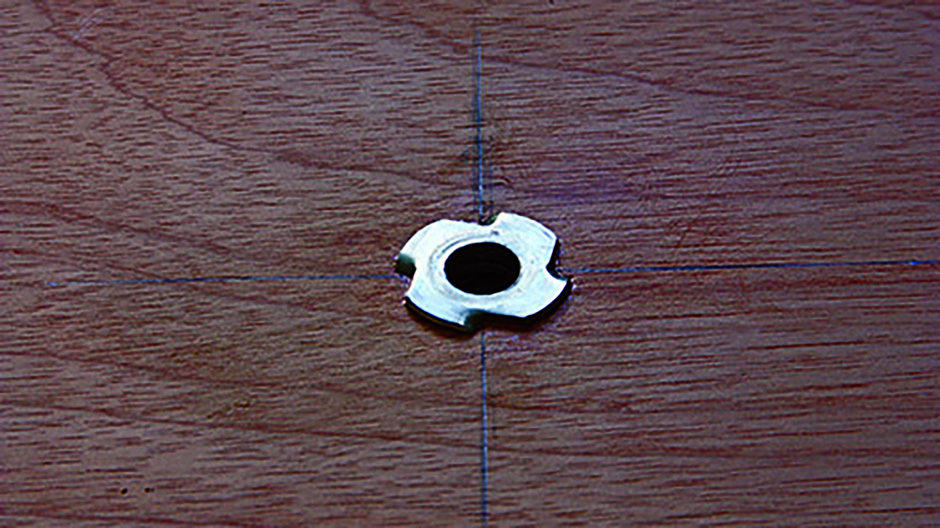
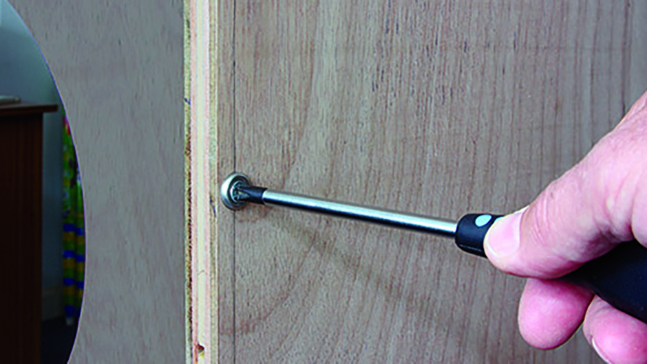
Lightly coat the outside of one of the T nuts with epoxy resin and pull it into the top of the base board using a 10mm bolt and washers until it is firmly seated.
Drill out the thread of the second T nut using a 10mm drill bit, and install it in the top of the rocker box base in the same manner – use a 10mm bolt, washers and nut.
Take one of the rocker box side panels and mark the centre point on its bottom inside edge; repeat for the other side panel.
Place the two side panels on top of the rocker box base so that the points you just marked match up with the line you drew across the base.
Now position the front of the rocker box so that it touches the two sides.
Mark its outside edge on the top of the rocker base.
Now mark the height of the front piece on the edges of the two side panels; trim these ‘horns’ so the side panels sit flush against the front panel.
Next, refer to Diagram 2 and drill out the nine 4.5mm holes in the rocker base as shown; countersink the holes on the reverse.
Fix the rocker base, front and side panels together using PVA glue and 15 No 8 1.5-inch screws (nine in the base, three in each side; these also need 4.5mm drilled holes).
Once the glue is dry, draw a pencil line perpendicular to the existing line (which you drew in Part 1) through the centre of each altitude wheel.
Centre the dovetail bar of your telescope on this line both vertically and horizontally, then mark and drill the two holes for attaching the tube rings.
Sand all the components and round the corners of the two bases.
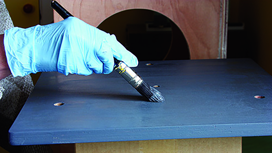
Apply two coats of external quality undercoat and topcoat paint to all surfaces, rubbing down between coats.
Then reduce the height of the screw base and centre tube sections of the adjustable feet to 25mm and attach them to the underside of the baseboard with epoxy resin and No 6 ¾-inch screws.
Bear with it
To make the azimuth bearings, cut the PTFE sheet into three 25mm square pads (unless you are using ‘Slide Glides’); secure these in the 1.5mm pilot holes in the rocker box base (see Diagram 1) using No 6 ¾-inch screws.
For the altitude bearings, cut four rectangular pieces of PTFE 25mm long by the width of the rocker box sides, then drill and countersink them.
Attach them to the top of the rocker box sides spaced as close as possible to 70° apart.
Assemble the rocker box on top of the baseboard, sandwiching the LP – which will act as a ridged bearing surface – as shown in Diagram 3.
Make sure you leave a 0.5mm gap under the bolt head before tightening the locknut underneath the baseboard.
Cut the edging strip to the correct width with scissors and attach it with impact adhesive to the perimeter of the altitude wheels, securing the ends with No 6 ¾-inch screws and cup washers.
Bolt the two circular retainers (the wooden discs you kept over from Part 1) to the centre top of the rocker box sides and apply felt to the inside surface.
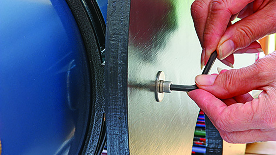
To finish, attach the altitude wheels to the tube rings, sandwiching the dovetail bars, using oversize washers on the outside.
Gently lower the altitude wheels into the bearing ‘cups’ to complete the assembly.
As a final option, you can use the swing of the telescope to determine the position for the attachment of a bracing bar.
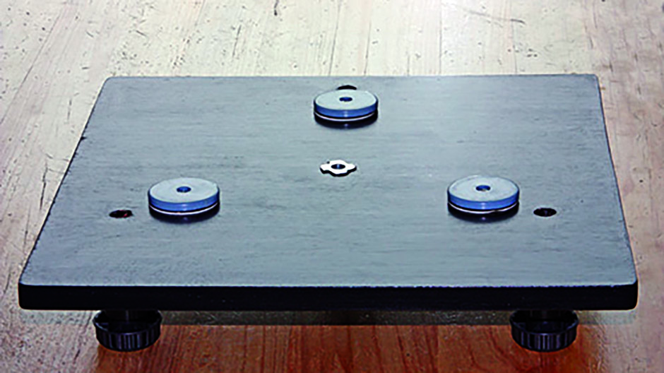 Cut down the height of the adjustable feet and install them on the underside of the base board.
