Dobsonian telescopes are popular instruments. They provide large apertures for a reasonable price and as such are suited to observing faint, deep-sky objects.
Their wide optics can also cope with high magnifications, but it can be tricky to keep celestial targets centred in the field of view in this situation, especially if – as is most common – your Dobsonian telescope has a manually operated altaz mount.
Here we'll going to show you how to build a motorised equatorial platform able to track the sky for an extended period (approximately one hour) before you need to adjust your scope.
Download materials to help with this project
- Instructions (PDF)
- Geometry and calculations (PDF)
- Geometry diagram (PDF)
- Bearing assembly (PDF)
- Bearing support block (PDF)
- North bearing segment (PDF)
- South bearing segment (PDF)
- Calculator (xlsx)
Tools and materials
Tools
Jigsaw, router, hacksaw, drill and bits, plane, spanner, Allen key, screwdriver
Materials
1,200x600mm sheet of 18mm plywood (this is enough for parts one and two of this project), 1m length of 30x30x2mm aluminium angle, 1m length of 12x2mm aluminium strip, A3 sheet of thin polycarbonate plastic or similar, 600x40x30mm offcut of wood
Sundries
Eight 608ZZ skateboard/roller blade bearings (22x8x7mm), eight M8x25 socket head screws, eight M8 washers, 16 M8 nuts, woodscrews, wood glue, double-sided tape
Finish
Wood varnish or spray paint
How it works

Our design makes use of circular bearing segments.
These are the easiest shapes to generate and provide good results for medium-sized scopes – our example project is based on an 8-inch, f/6 Dobsonian.
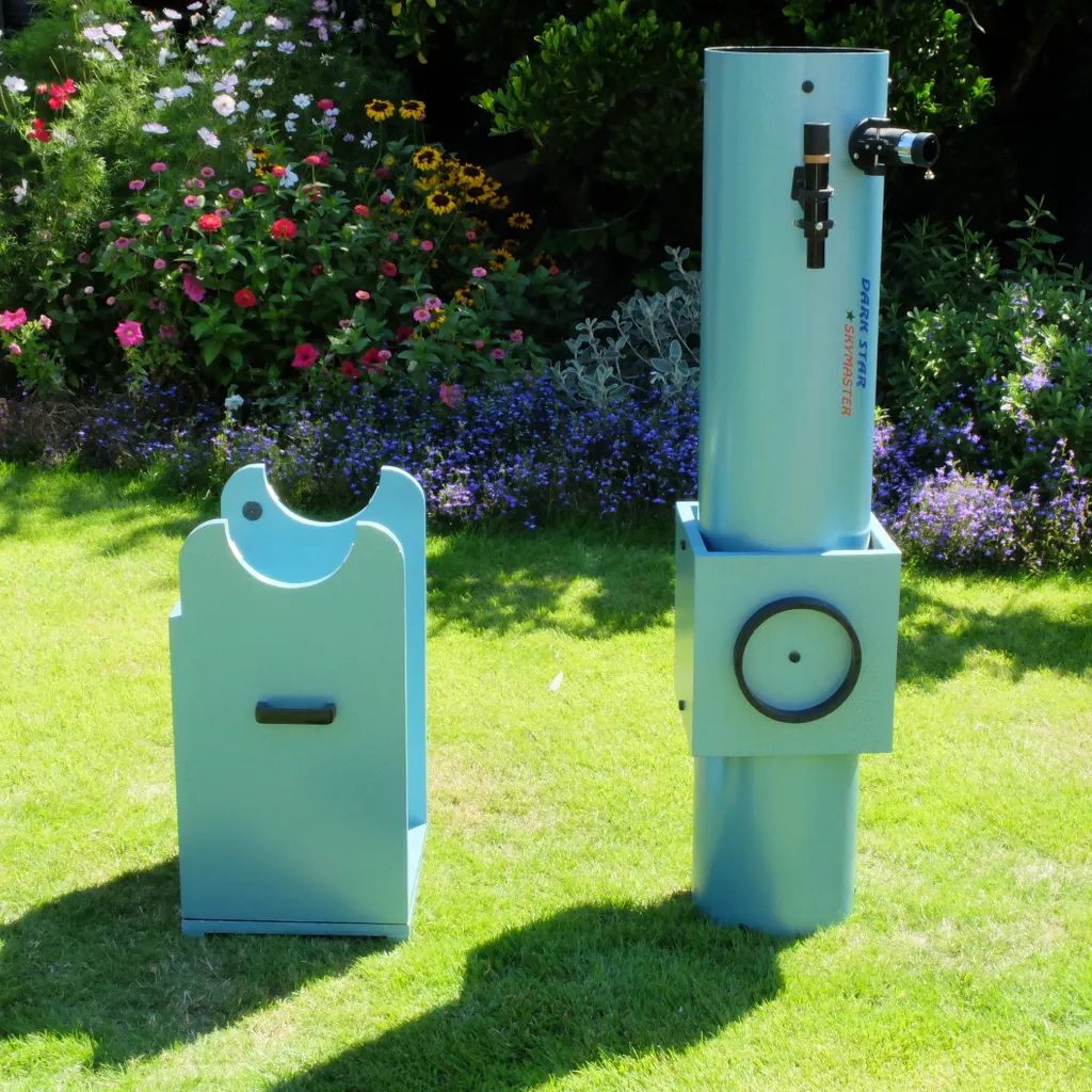
The principle behind it is quite straightforward: there is a fixed lower base board on which two sets of bearings are mounted, one set to the north and the other set to the south.
The upper, movable platform has two curved segments on its underside, which run in the bearing sets below.
The size and orientation of these segments ensure that the pivot axis of the platform is parallel to the Earth’s axis of rotation; hence we say it is equatorially mounted.
Finding balance
The platform is constructed from 18mm plywood and the bearings are 608ZZ skateboard bearings, which are inexpensive and readily available.
Their internal diameter is 8mm, so they are easy to mount using standard M8 screws.
Rather than have these running directly on the surface of the plywood, we added thin plastic sheets to the undersides of the segments with aluminium strips on the edges, providing tougher, smooth surfaces.
In order to calculate the size and angle of your segments you must know the latitude where the platform will be used and the height of the telescope’s centre of gravity (including its mount).
The segments are arranged so that this centre of gravity lies on the axis of rotation.
If it is too far above or below, the motor may struggle to drive the platform effectively.
The centre of gravity of the telescope will correspond to the centre of its altitude bearings.
You can find the centre of gravity of the mount box by balancing it on its side, and the combined centre of gravity will lie between the two.
Using moments, you can calculate the exact position.
Avoiding the maths

There is quite a lot of interesting maths involved in the design, which some readers will enjoy.
If you would rather avoid that, you can download our spreadsheet calculator from the link at the top of this article to generate the dimensions you need for the wooden parts after you enter some key values relating to your telescope.
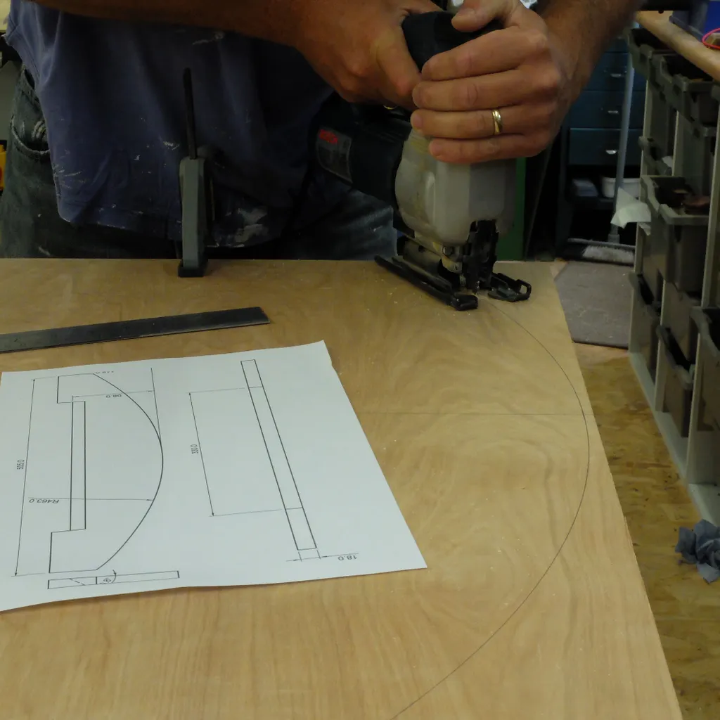
Cutting out the plywood parts is quite straightforward, but the curves do need to be smooth.
It is possible to do a good job by hand, but if you have access to a router then generating accurate profiles is easier.
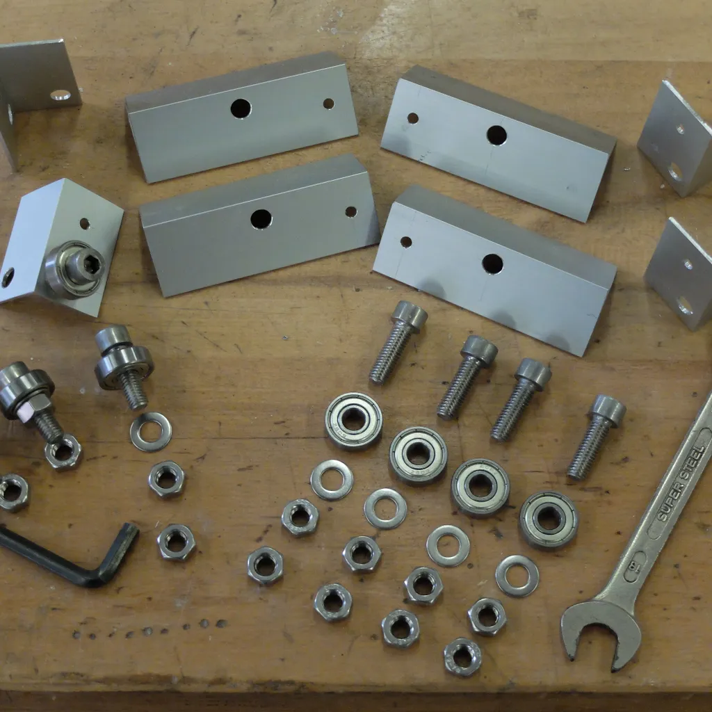
The bearings are simple to assemble using screws, washers and nuts.
Smaller ‘jacking’ screws make it easy to align the guide bearings, so they run freely without scrubbing, before fully tightening the M8 nuts.
Once you have assembled all your parts you will need to spend a little time adjusting your platform until it runs smoothly and checking that the north bearings make good contact, as these guide the telescope’s movement.
The south bearing assembly can be left to freely move or pivot on the base as it is only supporting the load vertically.
Motorising the platform

The next stage is be motorising the platform, completing the base board and setting up the mount for observing.
Commercial motor drives for telescope mounts are available for projects like this, but they can be expensive.
They use sophisticated stepper motors, which move by very small, predictable increments.
Short pulses are sent to these motors by a special controller to precisely control the motion of the scope.
One of these would be ideal but it is possible to build a cheaper (albeit slightly noisier) alternative.
Our drive is based on a more straightforward DC motor.
When the power is on, these motors turn fairly constantly, but quickly.
We used a home-made gearbox along with the gearbox built into the motor, and an off-the-shelf controller to modify the output speed to suit our needs.
Tools and materials
Tools -Jigsaw, router, hacksaw, drill and bits, plane, spanner, Allen key, screwdriver, hot glue gun, file
Materials - Remainder of 18mm plywood and 30x30x2mm aluminium angle from earlier in the build
Sundries - Modelling clay, worm, wheel, small spur gear, suitable axle (4mm rod), three M8x75 coach bolts with six M8 nuts, motor/gearbox (ours was 12V and 10rpm output speed), DC motor controller, M3 screws and nuts, M6 screw, Nylock nut and washers
Finish - Preservative wood stain or paint
Aim for sidereal

The principle behind our motor drive is simple: the telescope’s platform should rotate very slowly at the same rate as the Earth is spinning – the sidereal rate – but in the opposite direction.
In 24 hours this is only slightly more than one full revolution (360°), so in one hour the platform should turn 360/24 = 15°.
This is both a useful movement for observing and a sensible amount for our design to accommodate.
Since we know the radius of our north segment we can work out the length of a 15° section of the circumference.
After measuring the diameter of our output gear, we can work out how many times per minute it must turn to create the required movement.
This is the necessary output speed for our gearbox system.
To prevent slipping, the output gear drives a toothed section of the north segment.
We created this ‘rack’ by making a mould from modelling clay (rolling the output gear along a strip of clay to create the profile) then filling the mould with glue from a hot glue gun.
If you find this too fiddly, you can buy toothed belts with matching small gears instead.
Screw some stops onto the bearing strip to prevent the platform rotating too far either way.
The DC motor you need to buy should come with a built-in gearbox with a published speed of 10rpm or less.
A controller can also slow this down, so our homemade gearbox will only need to reduce the speed a little.
A worm gear with a wheel (ours has 57 teeth) will do the job nicely and these can be bought online.