How to build a star simulator

In this project, we’ll show you how to make a star simulator, a device that can be used within the home to both check and correct the collimation of a reflector so you’re able to make the most of your observing sessions.

Try out a subscription to BBC Sky At Night Magazine and pay just £9.99 for 6 issues today!
Published: April 4, 2016 at 11:00 am

Misaligned mirrors are one of the common causes of reduced image quality in reflecting telescopes, but one that can be solved with collimation.

It is true that there are a number of commercially available accessories that will generate artificial stars for this exact purpose.

However, most of these systems only work over long distances, sometimes up to 30m, which probably means an outdoor session unless you are lucky enough to have access to a large outbuilding or an unused warehouse.

The principle behind our DIY adaptation is that it can be used indoors at a distance of less than 7m – thereby making it possible to set up a test range in a hallway or a large living room.

Tools - Long nose pliers and ‘mini’ wire cutters, wire strippers, fine-tipped soldering iron, lead-free solder, junior hacksaw, electric drill and bits, needle file, bradawl, pocket multimeter.

Components- Solderless breadboard with at least 400 connection points; single-pole double-throw miniature toggle switch, 6A rated/12V DC compatible; 4.7kΩ linear rotary potentiometer with plain or splined shaft and a control knob; two resistors, one 270Ω ±1% tolerance and the other 2.2 kΩ ±5% tolerance; one 5mm round white superbright (20,000mcd intensity) LED and one 3mm round red LED, each 20-30mA rated.

Electronics- Project box with integral PCB guides, two stripboards to suit inner box depth, precision 10µm pinhole in mount, 5mm LED bezel mount, 16/0.2mm 3A stranded equipment wire, plus the components from part one.

Sundries- Fuse wire (5- and 15-amp); jumper wires with insulated solid tips (various colours and lengths); 9V long-life battery and snap on lead; double-sided foam tape for switch and battery attachment to the breadboard, insulating washers and tape, small ‘seat buffer’ to retain pinhole mount, cardboard disc to simulate mount diameter, marker pen, methylated spirit, dust mask, safety goggles, lacing cord or similar.

The task itself requires only minimal electronics knowledge and assembly skills.

At the end of your endeavours you will have built your own star simulator with which you will be able to reveal diffraction circles and bright centre spots to rival the star patterns shown in your scope’s user manual.

All of the parts required to build the simulator are easily available either online or from electronics stockists.

The circuitry is not complicated, but even so it’s a good idea to build a test setup on what is known as a ‘breadboard’ to check the arrangement of the components and to confirm everything functions correctly before you begin assembly.

First we’re going to focus on the star simulator’s circuitry using a solderless breadboard in readiness for test and transfer to the final control box.

Using a breadboard allows components to be placed and moved between sets of spring contacts, and also means you can try out your own circuits to improve performance.

For our purposes we used a double-pole double-throw (DPDT) switch with six terminals (of which only two were used).

You could alternatively use a single-pole double-throw (SPDT) version, which has three terminals with the centre ‘common’ and one ‘on’ connection being used.

To create a star...

To vary the intensity of the ‘star’, you need one of two basic types of single turn potentiometer, which we’ve designated RPA1 & RPA2.

The RPA1 has three ‘finger’ terminals set 5mm apart, often with a longer round shank, ideal for use with a breadboard circuit.

The RPA2 usually has solder terminals with a knurled shank.

For our project we used an RPA1, but if you have an RPA2 you can still attach it using short lengths of 15-amp fuse wire with one end bent through each eyelet in the angled terminals and bound with 5-amp wire to ensure good electrical contact.

The other (straight) end can then be adjusted to plug into the breadboard as with an RPA1.

In both cases the shank is usually 6mm in diameter to accept a control knob.

The light comes from LEDs, which are low-current and low-resistance devices.

Their polarity is characterised by a positive long lead (anode) and a negative short lead (cathode).

To prevent burn out, a resistor is placed in series with each LED to limit the amount of current that flows through it.

The LED limiting resistor values as calculated for our circuit are available at the link at the top of this page.
Step 1

StarSimulatorIStep1

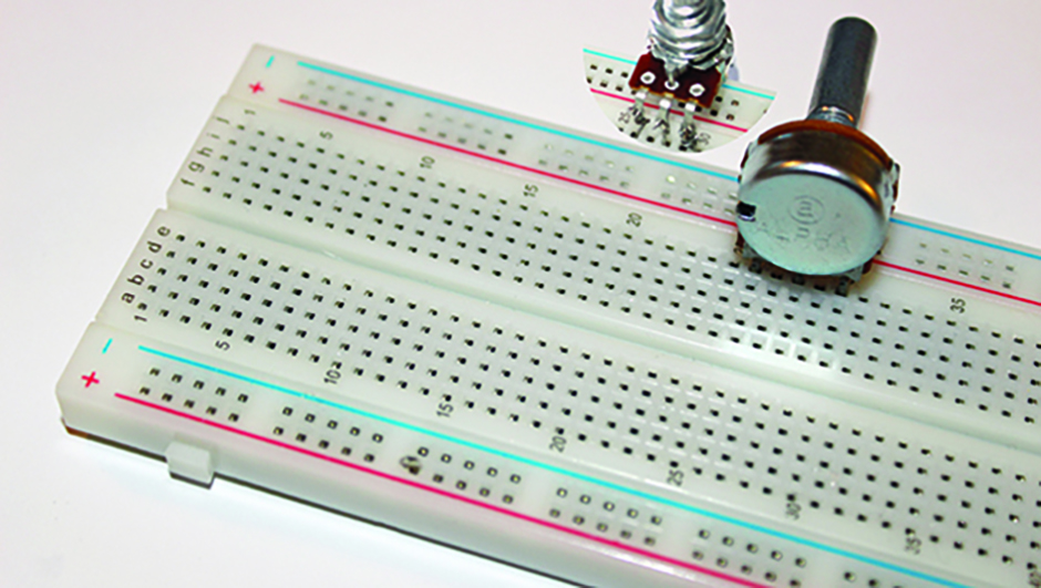
The breadboard uses alphanumeric notation – for example a10 or e22.

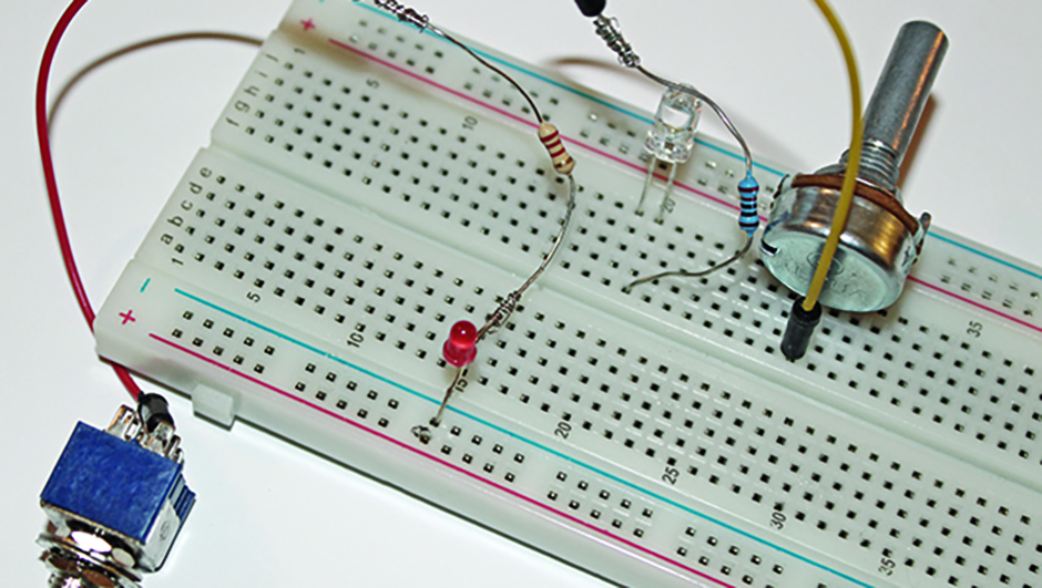
Mount the 4.7kΩ potentiometer in sockets j26 to j30. It may have a printed circuit board or solder lug mounting, and either is suitable.

This is the switch to vary the simulator’s intensity.

Step 2

StarSimulatorIStep2

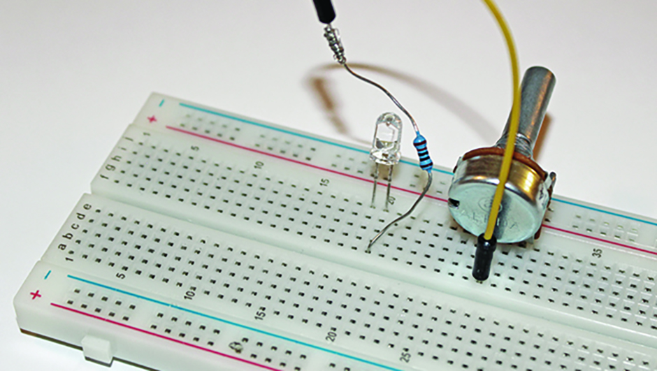
Mount the ‘star’ source LED in sockets j19 (cathode) and j20 (anode).

Bind one lead of the 270Ω resistor to a yellow jumper wire.

Plug the other lead into f20 and the jumper wire into f28.

Note that component wire binding uses 5-amp fuse wire throughout.

Step 3

StarSimulatorIStep3

Bind the 2.2kΩ resistor to a red jumper wire.

Feed the other tip through the switch (S1) ‘On’ terminal lug.

Bind the other lead of the 2.2kΩ resistor to the indicator red LED anode.

Insert this LED’s cathode into the negative track at row 15.

Step 4

StarSimulatorIStep4

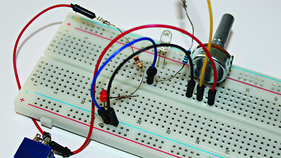
Now make the following wire connections: blue to f19 and the negative track by row 16; black to f26 and the negative track by row 17; and red to f30.

Feed the other end of the red wire up through the switch ‘On’ terminal to combine with the one shown in Step 3.

Step 5

StarSimulatorIStep5

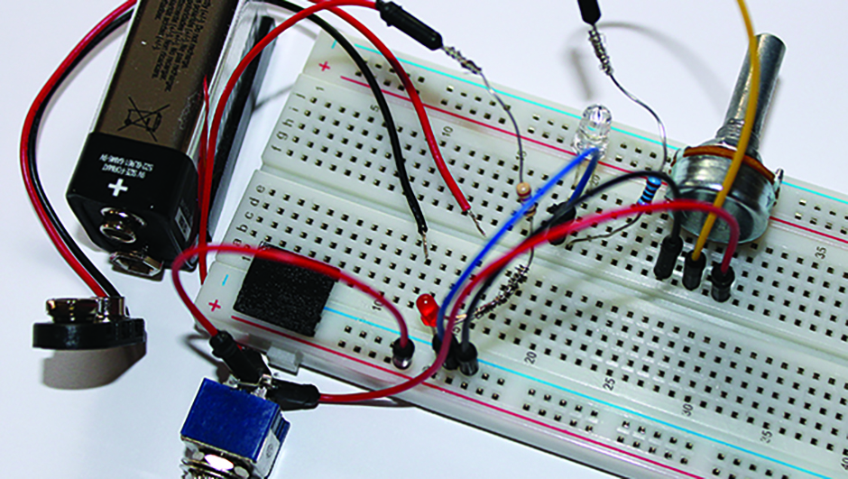
Plug a new red jumper wire into the positive track by row 13. Feed the other tip through the switch centre (common) terminal lug between the tip insulation of the two other jumper wires.

Secure the toggle switch and battery to the breadboard using double-sided foam tape.

Step 6

StarSimulatorIStep6

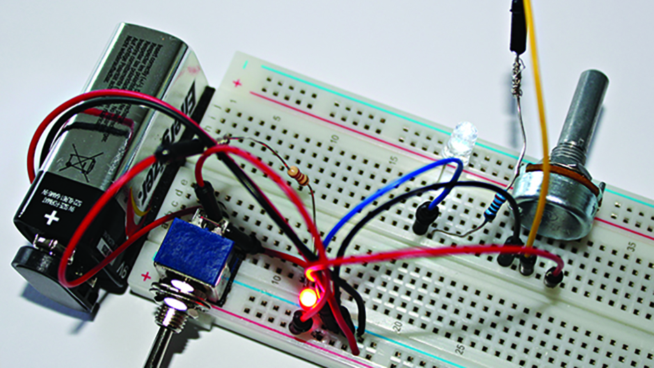
Plug the battery snap leads into positive and negative tracks by row 18, then connect the battery terminal clip.

Switch on and verify that the indicator LED illuminates, then operate the potentiometer and check that the LED ‘star’ varies from zero to maximum brightness.

Step 7

Now we are going to package these components into a device you can actually use.

In addition to the electronics mentioned, you also need a project box with integral PCB guides and a ‘star mask’.

The latter comprises a precision pinhole in ultra-thin foil and mounted in a 25mm diameter aluminium disc to provide a well-defined and bright ‘star’ source.

We can determine the ‘star’ size using basic trigonometry and applying the Dawes’ limit values usually to be found in the specifications for your telescope.

For a 4- to 5-inch reflector this works out at 13µm over a test range of 6.6m; for comparison, the thickness of a human hair is 17µm.

Precision pinholes are typically (but not exclusively) available in 5µm increments, so a 10µm size will give good resolution to an intense spot of light, such as given out by a bright white LED, at the set distance specified when directed through its microscopic hole.

Mark out and drill the end faces of the enclosure for the ‘star’ aperture, and the switch and indicator LED holes.

If required you can also drill the base of the enclosure to take a standard camera tripod attachment. Stripboards will form the basis of our permanent, soldered circuits.

It is important when cutting and filing board to always wear a mask to prevent dust inhalation.

Cut the stripboards with a junior hacksaw to fit width-wise between the integral guides, copper sides facing in.

Pilot drill the stripboard that will hold the ‘star’ through the ‘star’ aperture in the enclosure box, then remove the board and open the bezel hole in steps to full size.

Install the toggle switch and shape the rear board around it, maintaining two full tracks above to act as positive and negative rails.

Cover the top of the switch casing with insulating tape to isolate it from the copper strip.

Drill a hole in the enclosure lid for the potentiometer.

Mark the ‘HI’ and ‘LO’ (maximum and zero LED intensity) positions on the outside.

Solder the potentiometer leads to the terminal lugs.

Check this by connecting multimeter leads as follows: positive to the output (red wired) terminal and negative to the input (centre yellow wired) terminal. With the meter set to ohms turn the shaft between extremes. ‘HI’ should indicate 0Ω and ‘LO’ 4.7kΩ.

Remove the stripboards from the enclosure, then complete basic assembly by fitting the ‘star’ – the LED and bezel combination to the front board using insulating washers.

Insert a short length of wire insulation through the top centre hole in the rear board.

Feed the indicator LED anode through this and the cathode through the hole below.

Continue to make solder connections, mimicking the breadboard layout from earlier.

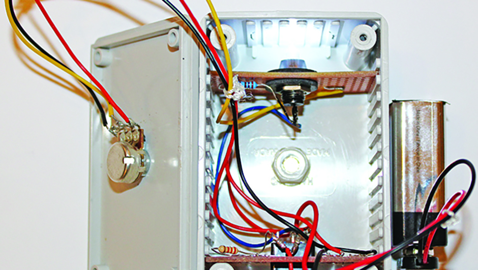
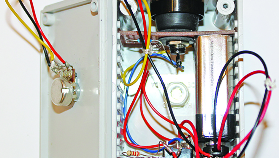
Replace the boards in the enclosure, routing and tying the wiring back to clear the battery partition.

Proceed with the pinhole mount installation as described in the documents available at the link above.

To use the star simulator, position it at 6-7m distance from the telescope and at the same height as its optical axis. Switch the unit on and adjust the intensity of the simulated star.

With the aid of a webcam and laptop, obtain the view of the star using the telescope’s focuser.

Defocus slightly to check for skewed images such as in the topmost of the images above.

Make small adjustments to the collimation while monitoring the view on the laptop screen, until the out of focus rings are concentric and collimation is achieved, as seen in the lower of the images above.

Step 8

StarSimulatorIIStep1

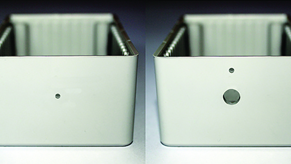
Work out the enclosure box’s centre line on the long axis.

Position the ‘star’ hole 16.5mm from one top edge and drill 3mm diameter (left).

At the other end, position the indicator LED and switch hole 5mm and 15mm down (right).

Drill 3mm and 5.8mm diameters respectively.

Step 9

OLYMPUS DIGITAL CAMERA

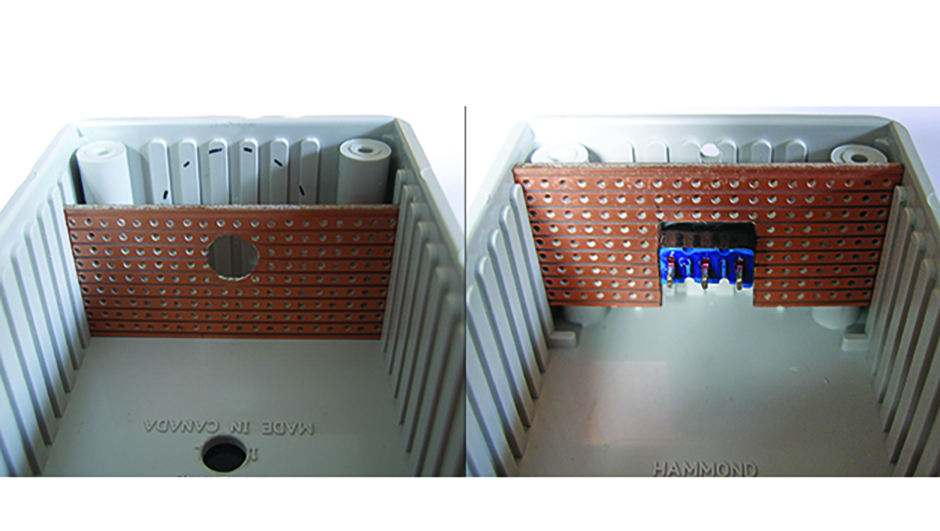
Drill a 3mm hole into the ‘star’ board (left) and open to 8mm.

Mount the switch and cut the board to fit around it, leaving two complete tracks above.

Cover the top of the switch (right image) with insulating tape.

Step 10

OLYMPUS DIGITAL CAMERA

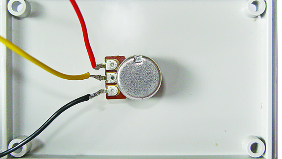
Mark the centre of the enclosure lid and drill a 6.8mm hole.

Mount the potentiometer so that the extremes of rotation are equal about the long centre line.

Cut and bare three 250mm-long wires (red yellow and black) and solder them to the terminals.

Step 11

[caption id="attachment_25392" align="aligncenter" width="940"]OLYMPUS DIGITAL CAMERA OLYMPUS DIGITAL CAMERA[/caption]

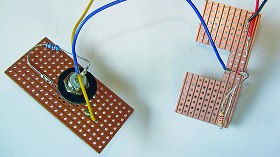
Attach the LED/bezel to the ‘star’ stripboard with insulating washers.

Solder the 270Ω resistor to the LED anode and board.

Cut and bare a 75mm length of blue wire and solder one end to the ‘star’ cathode.

Complete connections as per the circuit from part one.

Step 12

StarSimulatorIIStep5

Replace the interconnected strip boards in the enclosure.

Connect the battery snap and switch it on to verify that the indicator LED works.

Fit the potentiometer knob, aligning the reference mark with the HI/LO annotations.

Also check the ‘star’ LED varies in brightness.

Step 13

StarSimulatorIIStep6


Install the precision pinhole mount followed by the battery, taking care not to dislodge any solder joints.

Paint the rear flange of the ‘star’ LED black to prevent light leakage into the enclosure.

Check the unit operates once more, then fit the lid/potentiometer assembly.


Kim Clark is an amateur astronomer and a keen maker of astro-imaging devices

This website is owned and published by Our Media Ltd. www.ourmedia.co.uk
© Our Media 2024