Astrophotography takes a lifetime to perfect, but at every stage a little know-how and specialist equipment helps you to progress.
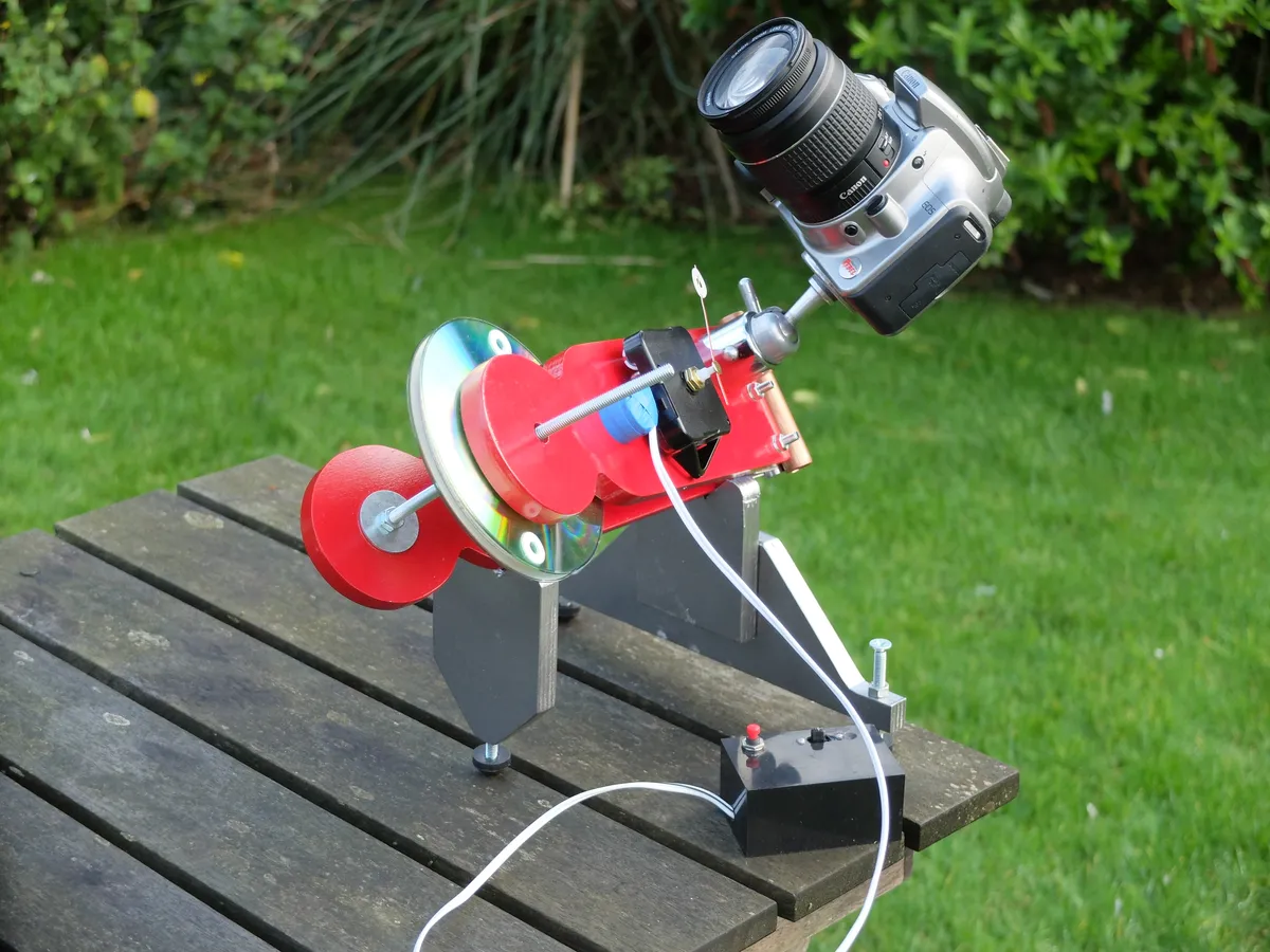
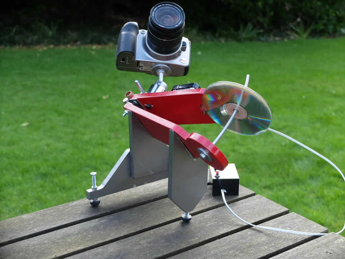
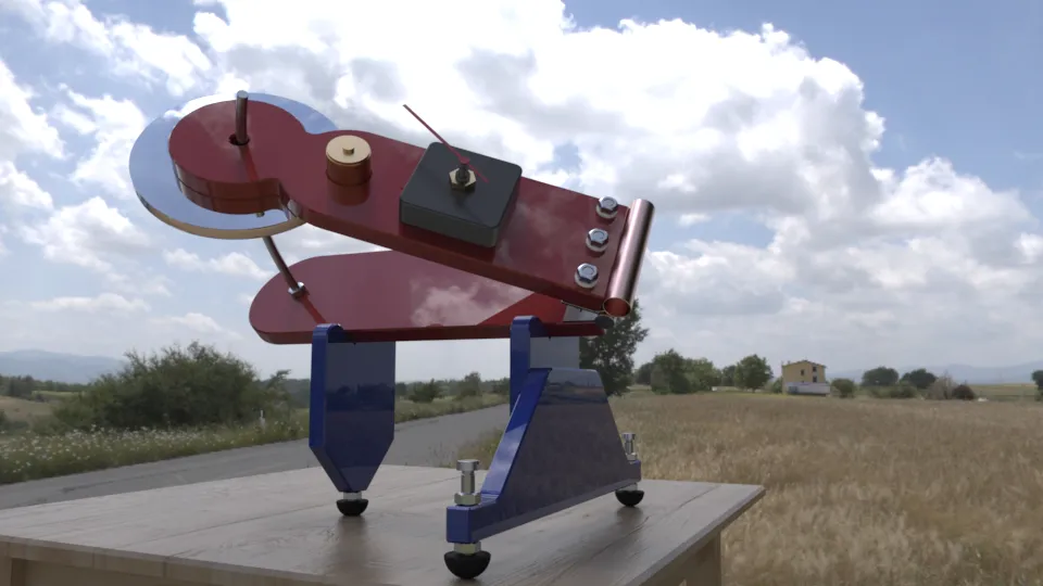
This project is a simple tabletop mount that can track the apparent movement of the stars, which allows you to increase exposure times and capture more light with your camera.
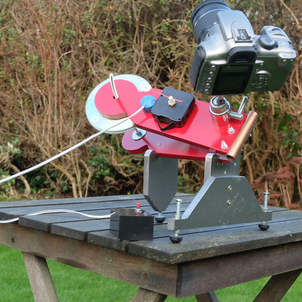
Once the mount is correctly aligned, you simply rotate a drive disc, which keeps your camera pointing at the same spot in the sky.
This well-known design (sometimes called a Scotch mount or a barn door tracker) can be made using materials found in most DIY stores and requires only minimal woodworking skills.
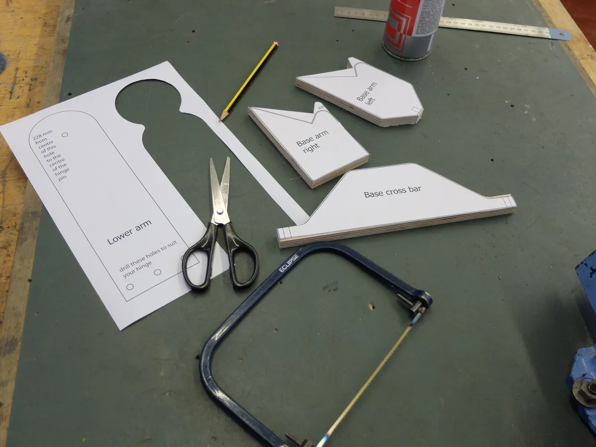
In this section, we are going to focus on the construction of the main elements of the mount and the drive rod – you can download printable templates for these below.
In the section below, we’ll cover the drive mechanism and describe how to operate it.
Downloads
- Table top tracking mount arms (PDF)
- Table top tracking mount base arms (PDF)
- Table top tracking mount base cross bar (PDF)
- Table top tracking mount main parts half scale (PDF)
- Tabletop tracking mount wiring diagram (PDF)
Tools and materials
Tools- Coping saw, drill with bits to suit the screws and rod, sandpaper, ruler, pencil, screwdriver, 10mm spanner or pliers.
Materials- Plywood (12mm thick, fine quality) for the arms and the base, scrap wood for the drive disc gauge.
Sundries- M6 studding (minimum length of 300mm), hinge, six M5x20 bolts and nuts for hinge, seven M6 nuts, two M6x40 bolts, three rubber tap washers.
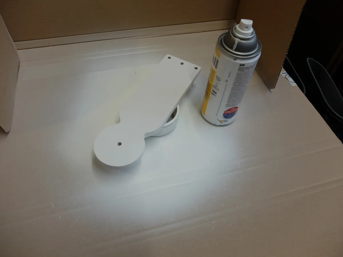
Finish- Exterior-quality gloss paint or spray paints for a nice finish.
Building on the basics
The principle behind the mount is simple.
Earth turns one full revolution every 23 hours 56 minutes and four seconds.
This period is called a sidereal day.
To an observer on Earth the stars appear to revolve slowly around the polar axis – which for the northern hemisphere is very close to the star Polaris in Ursa Minor.
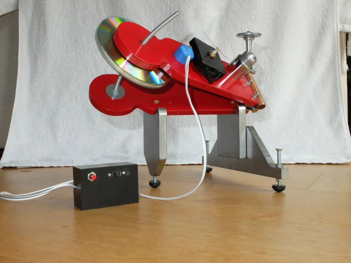
The mount has a hinged upper arm on which the camera is mounted, and the hinge’s axis is arranged to point towards Polaris.
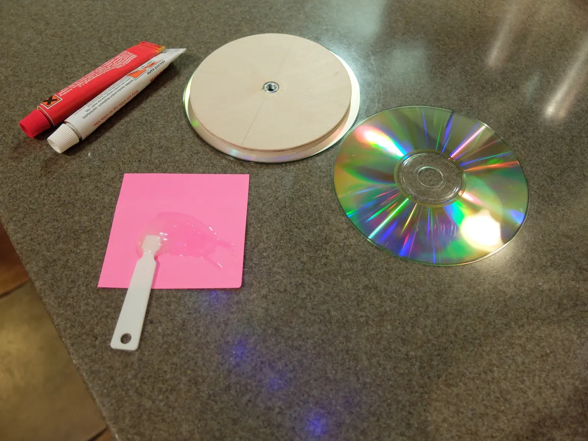
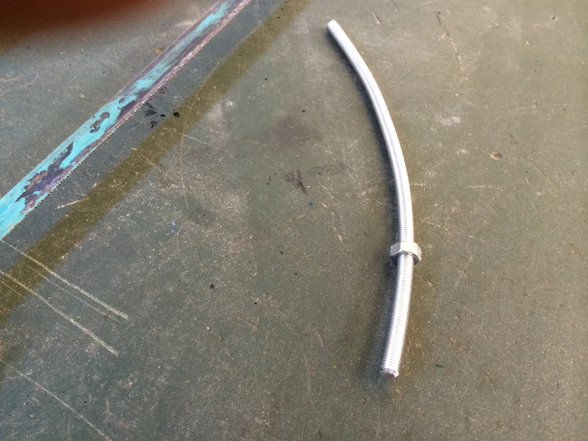
There is a threaded, curved M6 rod between the arms, and this has the drive disc on it.
Turning this disc causes the upper arm (and the camera) to rotate at the sidereal rate.
The clever bit is the maths.
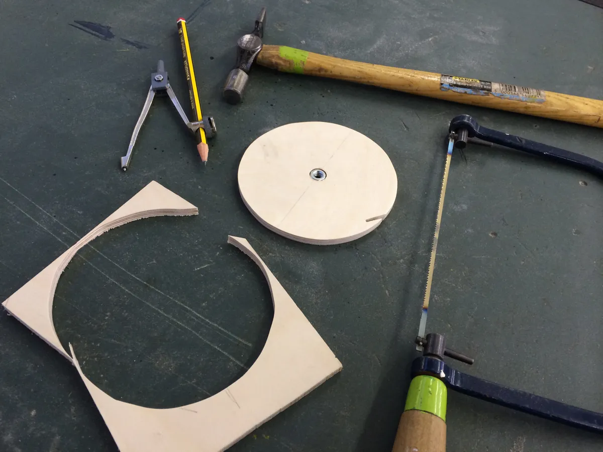
One full rotation of the disc on the rod causes the arm to move by 1mm.
For accurate tracking the centre line of the rod must be at the correct distance from the axis of the hinge – in this case 228.5mm.
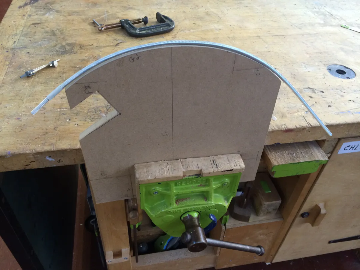
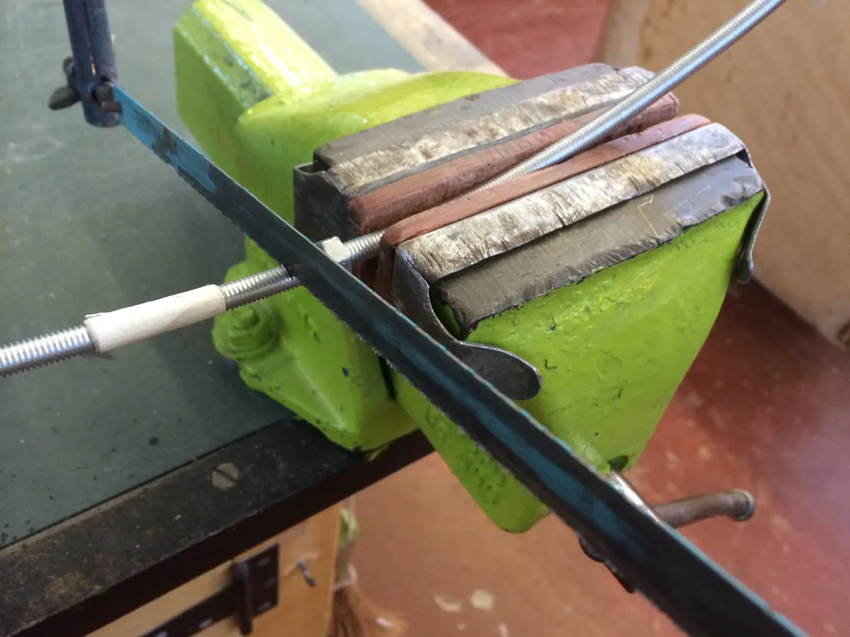
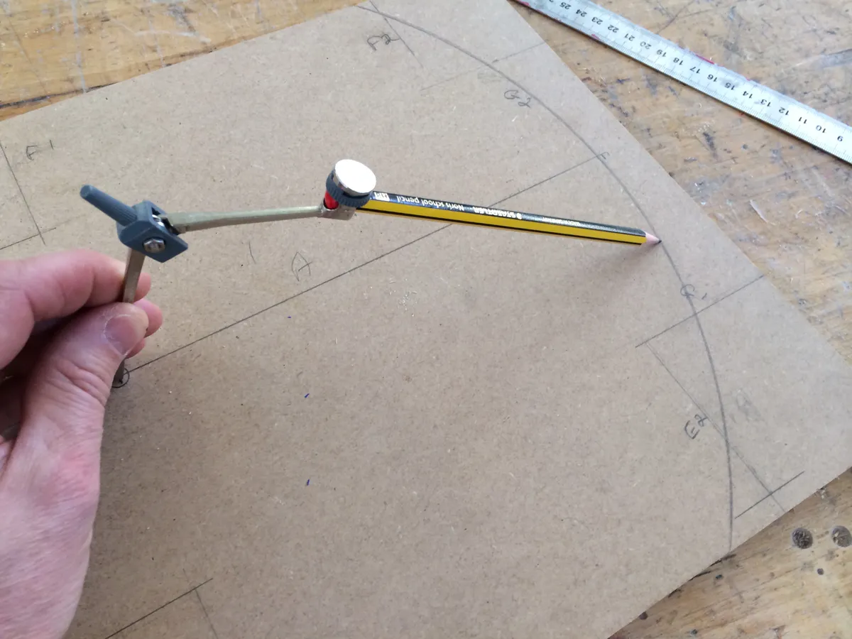
If this all sounds a bit technical or tricky to achieve, don’t worry, we have also provided a template, which you can use to bend your rod to the right shape, and the design is quite forgiving of a few inaccuracies.
We found that it is easier to bend a whole length of rod by hand, and then choose and cut the best section (you need approximately 200mm) for your mount.
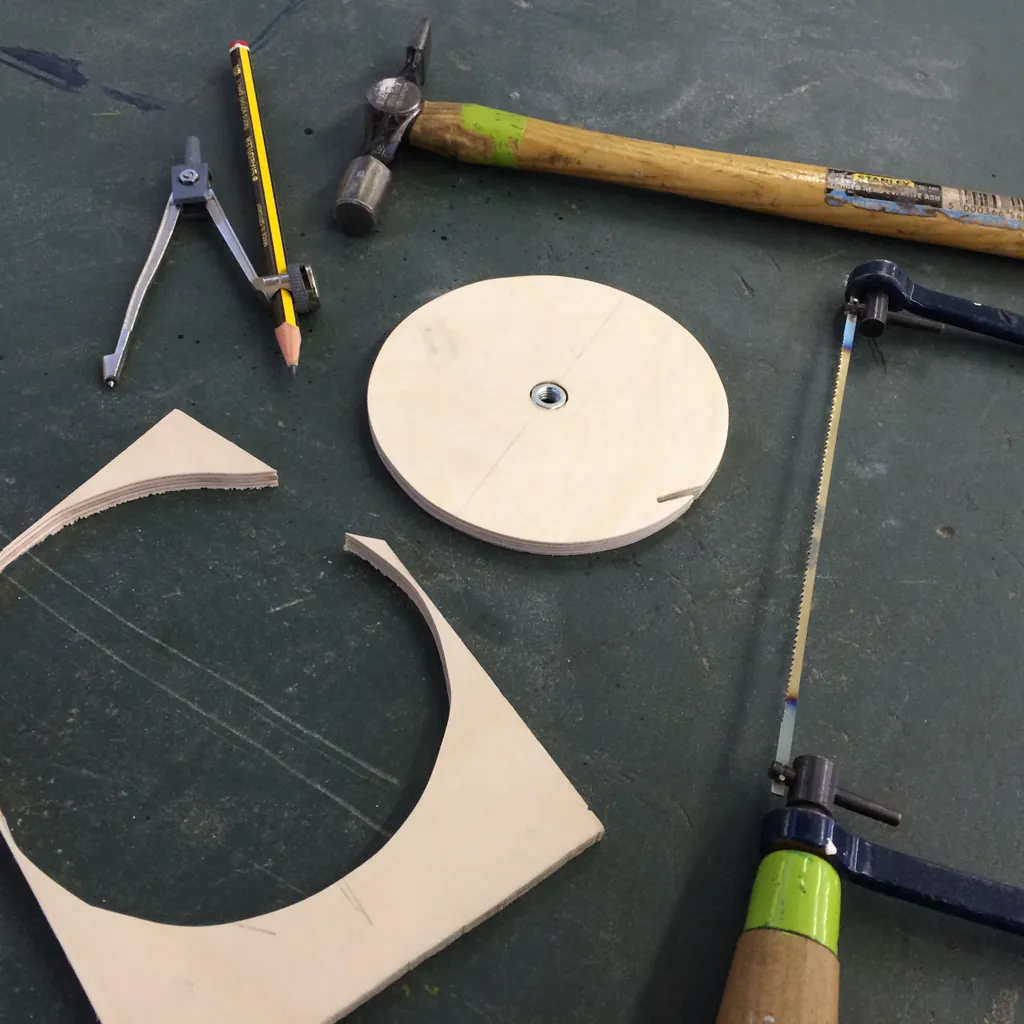
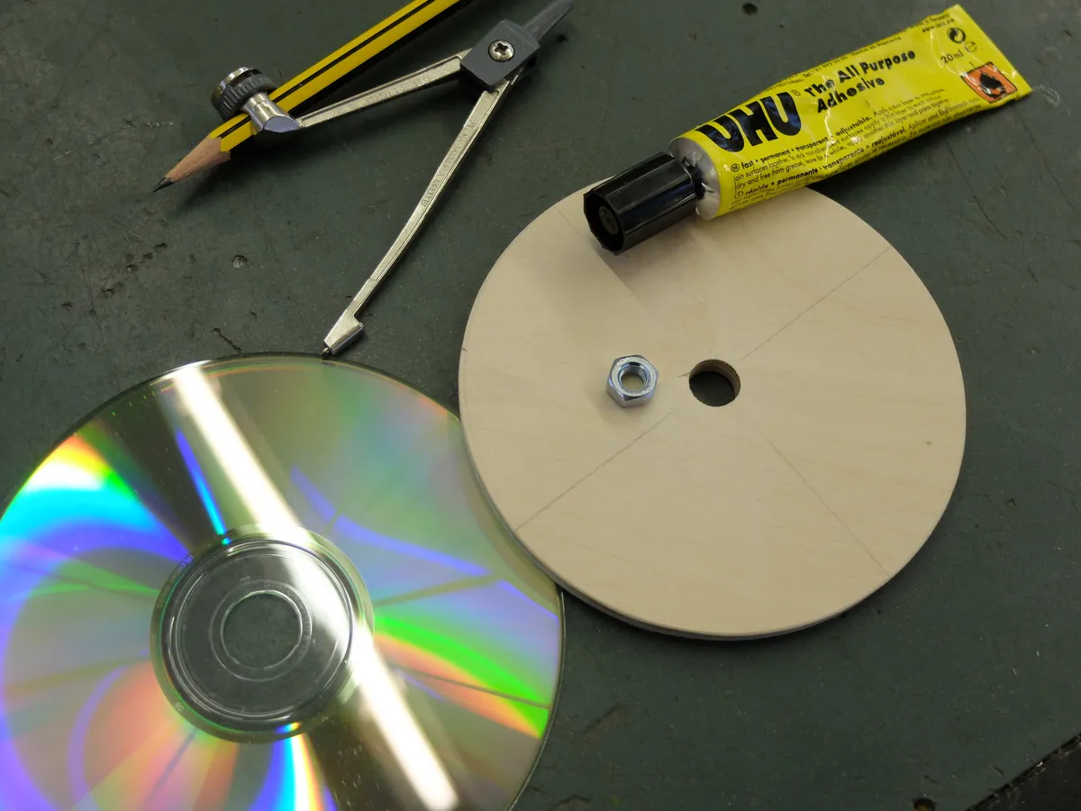
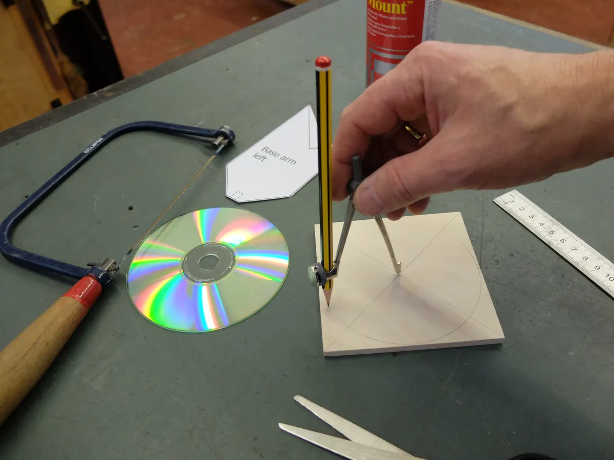
The main parts of the mount are made from strips of 75x12mm plywood, which is easy to cut.
Once you have printed out the A4 templates, lightly stick them to the plywood and cut around each shape.
The angled tops to the base arms need to correspond to your latitude, which will make polar alignment easier to achieve.
We made ours for 51°N; if you are in the UK you will be somewhere in the region of 50°-60°N.
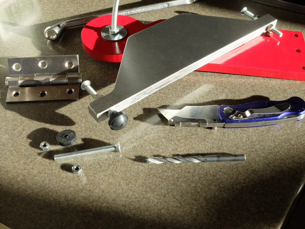
The hinge needs to move smoothly and not have too much ‘play’.
We found a good quality and inexpensive stainless steel one on eBay, but a reclaimed one from an old door could be a good candidate.
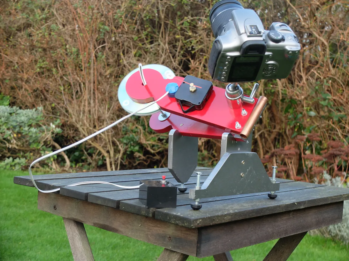
While you are shopping you also need a ball joint tripod head, which you will fix to the tracker.
This allows you to aim your camera in any direction.
These heads require a ¼-20 tpi screw (not M6 – even though the size might look similar) so you can fix them to the mount from below.
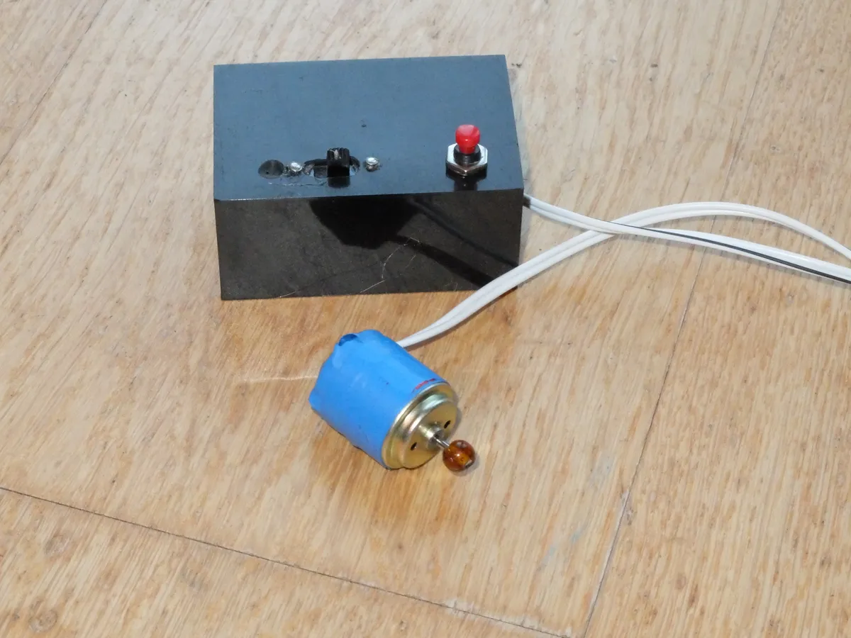
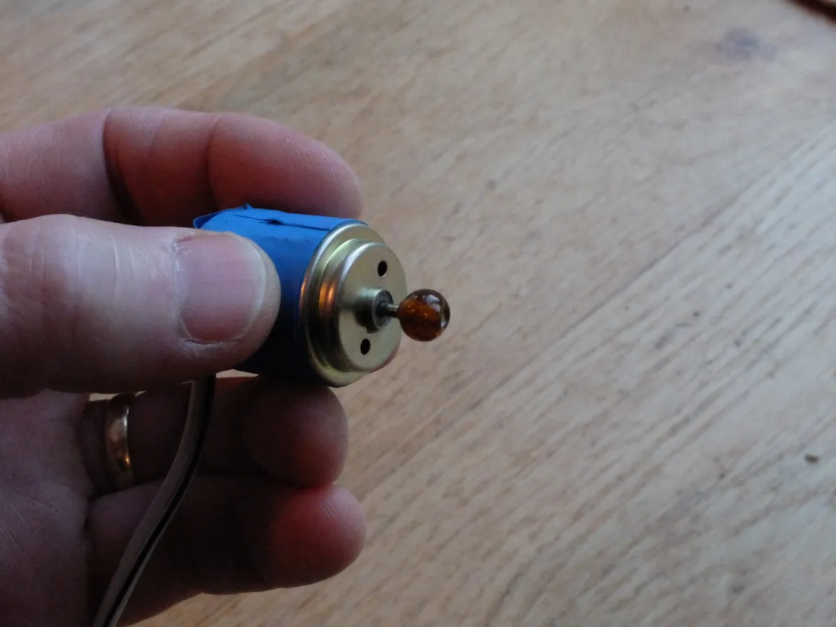
In the section below we will finish assembly and show you how to add a simple motor drive, but the beauty of a barn door tracker is that it works just as well when hand-driven, and there is something very satisfying about the interaction involved.
The drive wheel doesn’t need to be turned constantly – just keep the average rate at one turn per minute.
Image gallery