The Dobsonian mount is well known for its simplicity of use: locate an object by star-hopping to it and then give the mount a gentle nudge every minute or so to keep it within the view of your eyepiece.
However, many deep-sky objects can be rather difficult to find as they are so dim that they can’t be seen in your finderscope.
The use of setting circles can make this task a little simpler by allowing you to point accurately to anywhere in the night sky.
Although the RA and dec. coordinates of almost all celestial objects visible to amateur astronomers are readily available, they can’t be used with an altaz mount such as a Dobsonian.
Download our azimuth card (PDF) and azimuth diagram (PDF)to help you complete this project.
Altaz mounts instead rely on altitude (degrees above the horizon) and azimuth (degrees clockwise from due north).
And, unlike RA and dec., the altitude and azimuth of a celestial object constantly change with the movement of the sky overhead.
This constant shifting means that, with an altaz mount, you will need to refer to a planetarium program to find the positions of objects you want to see through the eyepiece.
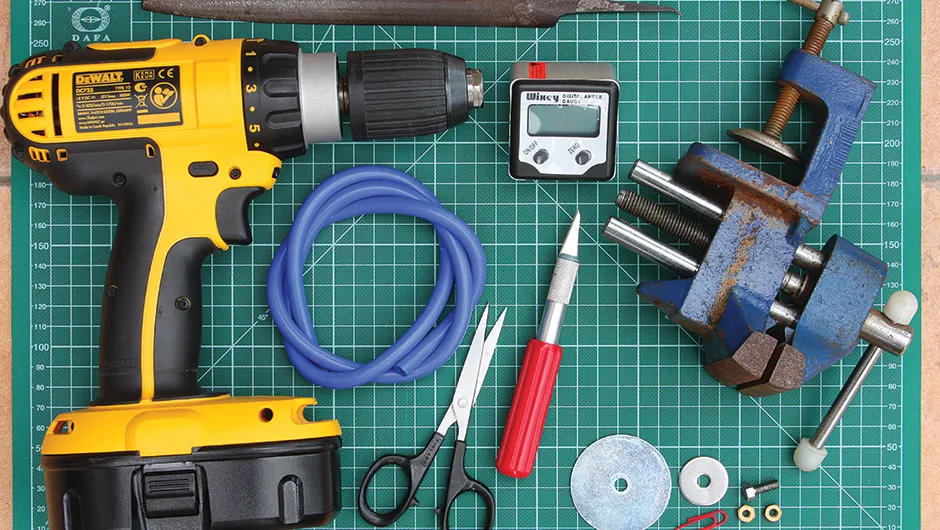
Electronics - A digital inclinometer – various makes are available, including Wixey, Minipro, Bevelbox and Digi-Pas.
Materials - A vinyl record to act as a ‘table’ for the setting circle. Ask a local printer to reproduce the setting circle on card and laminate it.
Sundries - A 2BA x ½-inch bolt, two 2BA nuts, two penny washers and a small section of silicone vacuum hose are required to complete the assembly; you’ll also need a paperclip and epoxy resin to fashion a pointer.
Tools - Hand file and bench vice to modify the mounting bolt, scissors and craft knife to trim the setting circle template, and a hand drill to create the hole for the pointer.
Breaking convention
Let’s say you know the position of the object you want to observe.
The altitude of the telescope can easily be set by using an electronic inclinometer, but for the azimuth, a calibrated 360° setting circle is required.
Conventionally, this would be installed on the baseboard and read through a peephole in the base of the rocker box.
In our design, we make use of the fixed azimuth bearing bolt that is attached to the baseboard.
This bolt has an Allen key cap and the azimuth setting circle simply presses into the hexagonal cut-out in the head.
We’d recommend printing the setting circle on card via the link above and then giving it a matt lamination, as this will reduce any reflections that would make the scale difficult to read.
We also used a vinyl record to support the card.
Your first task is to modify the hexagonal head of a 2BA bolt by filing each of its six sides evenly until it is an interference fit (ie, it holds by friction) inside the head of an M10 azimuth bearing bolt.
Hold the bolt head (not the thread) in a small vice and file each side in turn.
To make a firm but adjustable bearing to support the vinyl record, cut a 2mm ring from a length of silicone vacuum hose and press it into the centre of the LP.
Finding your position
Cut a 5mm hole in the centre of the azimuth circle and then assemble the unit with the modified 2BA bolt, 2-inch M6 penny washer, vinyl record, setting circle template, 1-inch M6 penny washer and two 2BA nuts as shown in the downloaded Assembly Diagram.
Tighten the 2BA nuts against one another to lock them.
It is not always possible to arrange for the mount’s baseboard to be correctly orientated to north so we have designed the azimuth setting circle to allow for simple calibration.
First, point the telescope at Polaris (nominally 0°) or centre a known star in the eyepiece.
Then rotate the setting circle until the pointer aligns with the star’s azimuth.
The scope can then be set to any azimuth by rotating the rocker box until the pointer aligns with the required angle.
The telescope’s altitude angle can be set by placing the digital inclinometer on the rocker box base and setting it to zero then placing it on the telescope and adjusting the telescope to read the correct angle.
Take a look at more of our DIY builds: